Cascadable Intelligent Power Switches
CIPS are a low-cost power switch for automating the control of DC power to devices without sacrificing features. The switches are infinitely cascadable and require no software configuration, instead self-addressing by their position in the daisy chain. The switches communicate over a simple half-duplex serial interface, and are able to report back current and voltage measurements.
Table of contents
Hardware
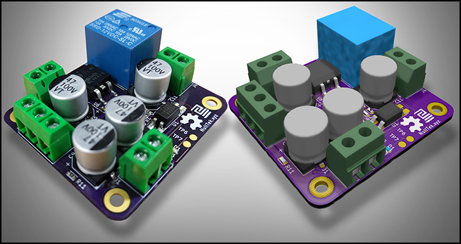
The switch can be build in several configurations depending on the requirements of its application. There are pro’s and con’s to each setup.
| Configuration | 1-12V Switching | Single Source Supply | Cheap BOM |
|---|---|---|---|
| CVIR | ☑ | ☒ | ☒ |
| CVSR | ☒ | ☒ | ☑ |
| CVIS | ☑ | ☑ | ☒ |
Control Voltage Independently-Regulated (CVIR):
This is the default configuration. It uses a second power supply with a common earth >12V which is regulated down to 12V on the CIPS. It is the safest most reliable configuration because it doesn’t need to be piggybacked on the source supply and gets the additional line regulation benefits from the LDO.
Control Voltage Source-Regulated (CVSR)
This is the simplest configuration in terms of wiring complexity. It allows the CIPs 12V control voltage to piggy back off the primary source supply. This relies on the source voltage being 12-30V, which is often the case in reality.
Control Voltage Independently-Supplied (CVIS)
This configuration is the cheapest because it doesn’t require U6 to be populated. It relies on the regulation and stability of an external control supply.
Software
The switch uses a single-wire serial implementation as it’s low level method of communicating bits, and on the higher layer it uses NPC as an error resistant method of processing bytes.
Single-Wire Serial
In this system each switch is a slave to the previous switch in the serial chain, with an endpoint master device controlling the cascadable network. This means each serial link has single-slave and a single-master endpoints. The link is an open drain wire that is pulled up to 5V, this is so that a break in the link to the master can be easily detected. Since the CIPS switch favors a low BOM cost it uses the internal oscillator on the PIC microcontroller, which is the limiting factor max bus-speed that is possible without synchronization errors. Running at 32MHz +/- 1% gives a theoretical minimum pulse length of 31ns with 640kHz inaccuracy window on the source clock, so in reality pulse duration of less than 3us are not stable enough for communications. Also due to the sacrifices you make in high-level compilation / soft interrupts I will use a conservative pulse duration of 100us.
The master will initiate a transmission with a reset pulse of 500us. The slave will subsequently respond with a presence pulse of 100us once the master releases the bus. This handshaking completion shows the slave is ready to receive data from the master. At this binary data is sent across the bus using the NPC protocol.
Cascading High Level Communication
The system uses a full implementation of Null Packet Comms. The switches do not know their own location and only determine which data is applicable to them by the order of that packet in the serial stream, similar to cascading addressable LEDs. Each switch will assume the first packet is for itself, and pop it off the stack, then act as a repeater for the following packets without actively inspecting them. All instructions are acknowledged by the switches, followed by any response packets to query instruction. Response packets are only sent by a switch once it has received a response from it’s neighboring slave switch or a timeout triggered. A switch knows how many higher order switches exist by the number of additional packets it repeated, it has no knowledge on lower order switches.
The limitation of this cascadable 1 wire paradigm, is to communicate with switch index ‘n’ you must send at least n-1 control packets. However if you are just interested in performing the action on the nth switch, you can populate all n-1 previous packets with a ‘ping’ request which will decrease latency as the instruction is quick to execute on the switches. To avoid confusion and increase consistency it is recommended to always send the same number of control packets as switches in the serial chain.
Use a subtractive bit-mask voltage when converting to integer to remove the irrelevant data. Eg: When acquiring current zero the first 14 bits so they don’t alter the result and vice versa.
Embedded Software
The onboard 12F1572 8 Bit PIC microcontroller was developed using MPLAB IDE. The code is written and C and can be compiled using the MPLAB XC8 Free Compiler.